- Home >
- blog >
- Tips & Best Practices >
- a-look-at-adjusting-and-wiring-joystick-potentiometers
A Look at Adjusting & Wiring Joystick Potentiometers
Ready to adjust and wire your potentiometers and not sure where to start? The first point to understand is that the joystick does not determine the supply voltage. The supply voltage requirement is determined by what the drive of the machinery requires for a reference signal.
To help illustrate the process of adjusting a potentiometer, we have prepared some typical examples below. Please note that the pot terminals are identified as follows:
R = Right*
L = Left*
W = Wiper
T = Center Tap
*R and L are commonly also referred to as CW (clockwise) and CCW (counterclockwise) terminals.
Plus/Minus Control (4-Wire Potentiometer)
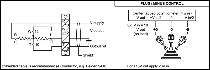
In this example, we look at a standard plus/minus control configuration for a 4-wire potentiometer. With a 10VDC input there will be a plus/minus 5VDC output. Depending on the directional polarity requirement, the input of power and ground may need to be swapped. In one direction there will be 0 to minus 5V and the other direction will be 0 to plus 5V. This wiring style divides the voltage in half.
The diagram above shows positive 10VDC wired to terminal R. The ground is wired to terminal L. The output on terminal W and the reference output will be on T. Terminal W would be the positive to the meter or drive and T would be the negative to the meter or drive.
Plus/Plus Control (4-Wire Potentiometer)
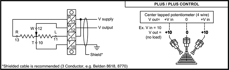
This second example breaks down plus/plus control for a 4-wire potentiometer. With a 10VDC input there will be a plus/plus 10VDC output. There will be 0 to plus 10V in one direction and the other direction will also be 0 to plus 10V. This wiring style provides the same positive output in each direction as the input.
The diagram above shows positive 10VDC wired to terminal R and jumpered to L. The output is on terminal W and the ground is wired to T. Terminal W would be the positive to the meter or drive and T would be the negative to the meter or drive.
Plus (Throttle) Control (3-Wire Potentiometer)
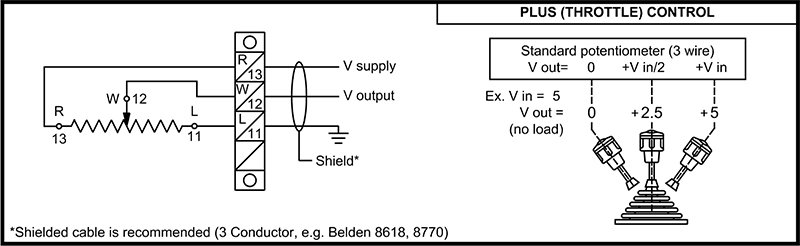
In this example, we look at plus (throttle) control configuration for a 3-wire potentiometer. With a 5VDC input you will get up to 5VDC out. The input of the power and ground may need to be swapped depending on the directional polarity requirement. If the potentiometer is mounted on a spring return to center joystick or a friction brake joystick with a center detent, the starting position of the joystick will be plus 2.5VDC in the center. As you move the handle in one direction to the end of the handle travel there will be 0 and plus 5VDC in the opposite end of travel.
The diagram above shows positive 5VDC wired to terminal R. The ground is wired to terminal L. The output on terminal W, which would be the positive to the meter or drive
Still have questions about wiring potentiometers? Contact us and one of our technical representatives will be happy to assist you.